Parts-Crib
(Week 12) Nov/28/19
presentation has been compleated. Link to pres
Progress Report:
Everything is on scedule and no notable changes have been made to the budget. I got the output to work properly and I can see the output through putty. This makes it easier to code the distance tolerance to turn on LED.
(Week 11) Nov/20/19
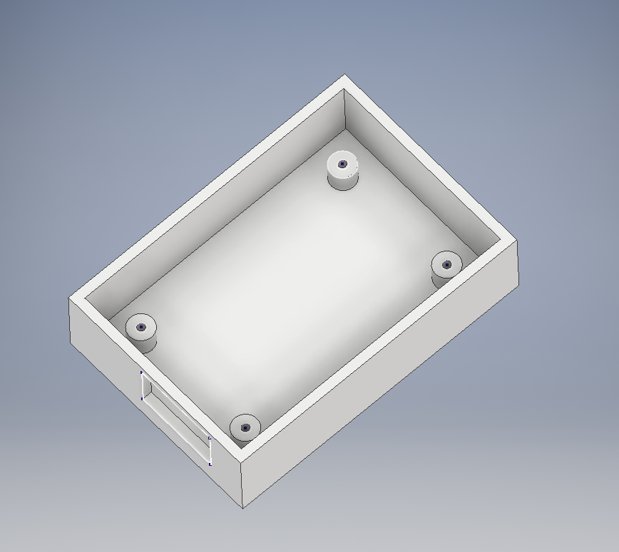
Enclosure has been compleated and the following image is from autoCAD which is where the object was crated
Link to stl and dwg files
Progress Report:
Everything is currently up to date and the case was printed and fits my PCB well. To make the 3D model, I used AutoDesk Inventor and AutoCAD. I first made the model in Inventor then expoted it to AutoCAD so I could then export it as a STL file. The only problem I had is that the PCB is mounted to the case woth 4 M3 6mm machine screws. In Inventor, I used the hole command to thred the inside of the cylinders that hold the PCB up and allows me to screw the PCB to the case. However, because of the ammount of time I can use at the 3d printer, I had to increase the layer size which didnt thred the holes properly. To fix this I used a treading drill bit and threded the holes myself. No notable changes have been made to the budget or plan.
(Week 10) Nov/14/19
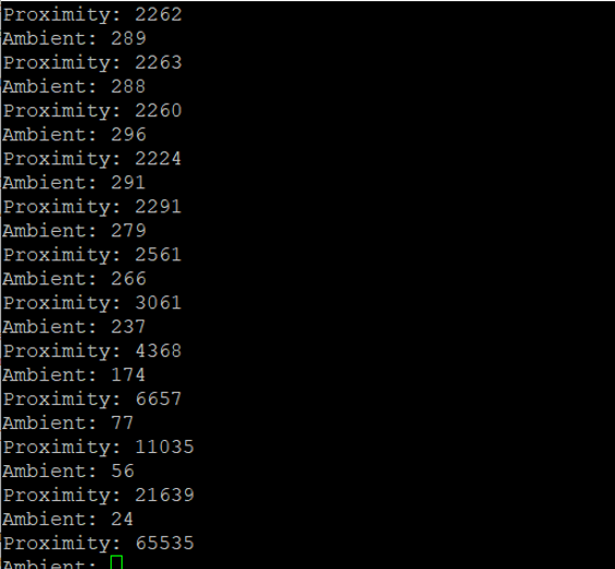
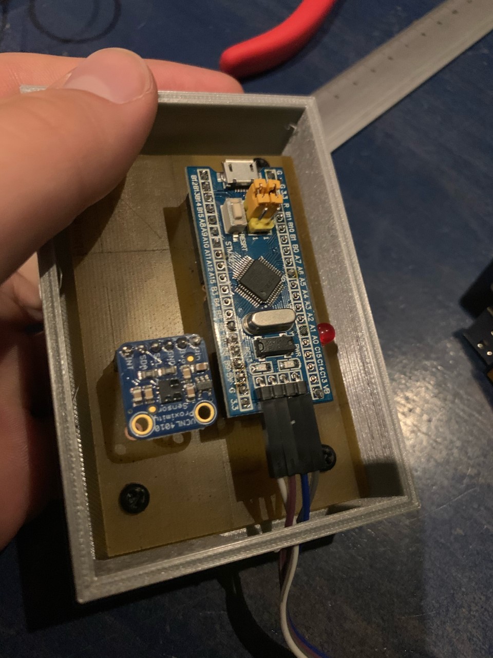
PCB Powered up and is working.
Following is the nothing infront of the 4010 Proximity Sensor:
 Following is when there is something (My Phone) infront of the proximity sensor:
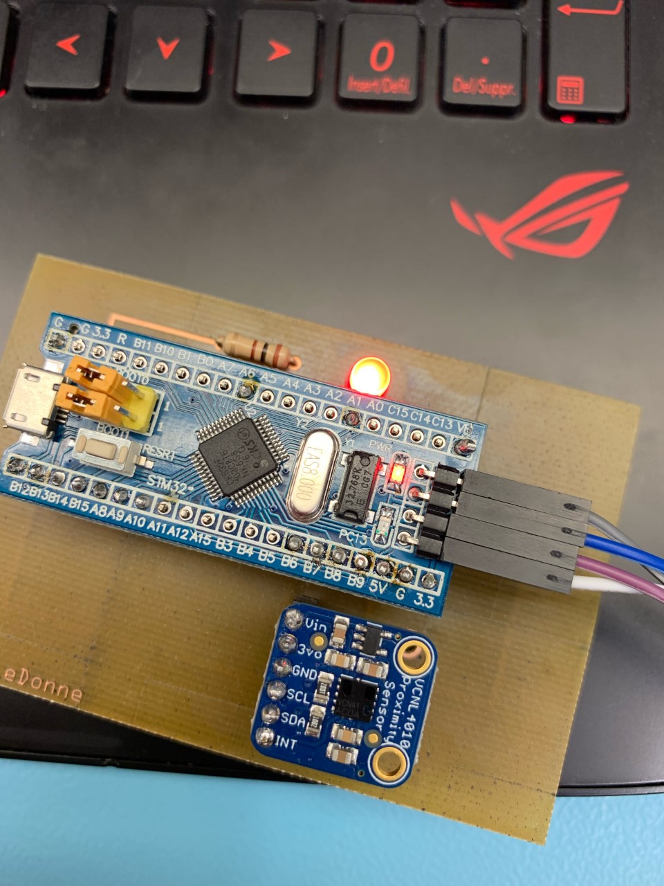
Progress Report:
Everything is working as intended so far on the PCB. Today my professor noted how to use the serial monitor with the STM32 and I will try to get that working sometime this week. It will be useful to see the serial monitor as the code outputs the distance from the proximity sensor to the serial monitor. This means I can see the exact values for how far something is away form the sensor and I wont have to guess the number to put into the code. This will be especially useful when designing my case as I need to make sure that the sensor does not detect the case, but will detect something outside of the case (i.e a phone). I am currently working on a case for my PCB and should have it printed by next week. No notable changes have been made to the budget or overall project. As long as I get my case done by next week, everything will be on schedual according to the proposal.
(Week 9) Nov/07/19
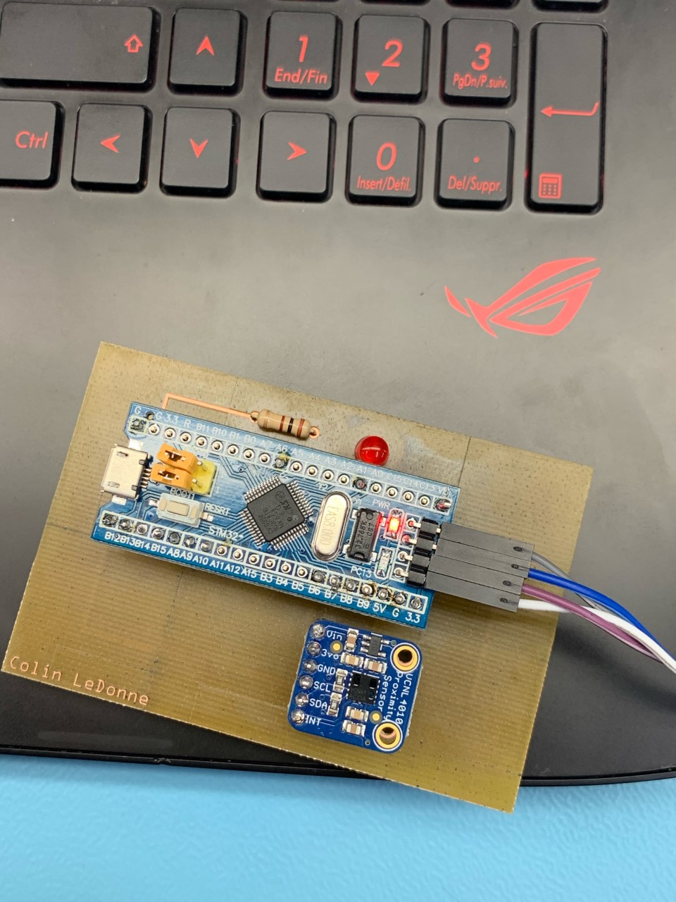
PCB Soldering. The following is the complete soldering:
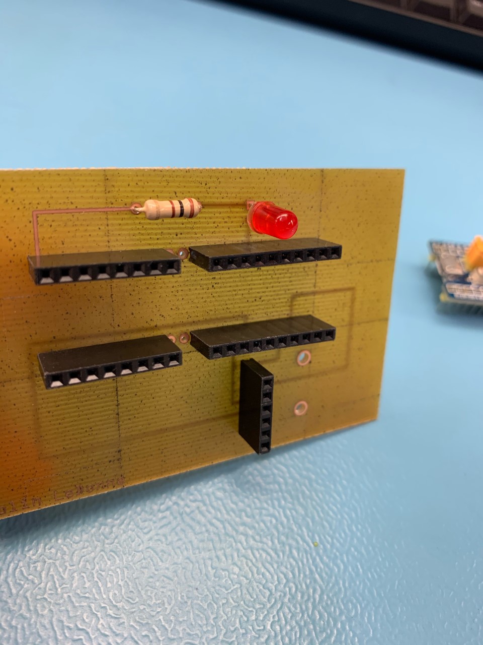
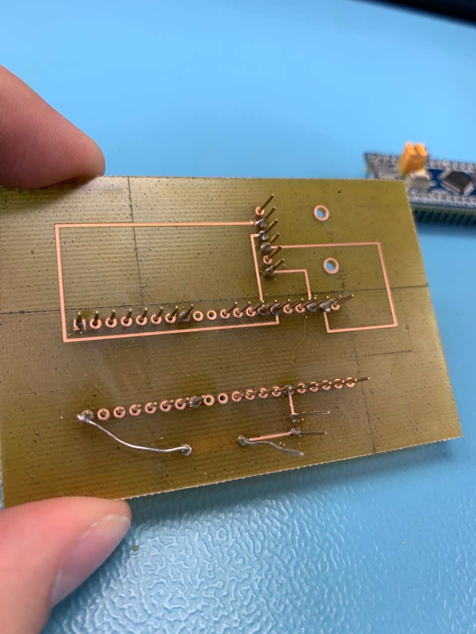
Progress Report: Everything on the PCB was fine expect the connection from the resistor to ground was printed on the top of the board instead of the bottom. To fix this, I simply soldered the wire from the resistor to the ground pin on the bottom of the board. This can be seen in the images from above. All connections are fine as there is no resistance from power to ground which means there are no shorts in the PCB. The project is on time and no notable changes have been made to the overall project.
(Week 8) Oct/31/19
Breadboard Milestone Breadboard has been completed and is functioning. One thing to note is that there is no output screen since the STM32 does not have a serial console; so I can only show the breadboard working. Link to the code for the STM32: Link
The following pictures are the breadboard:
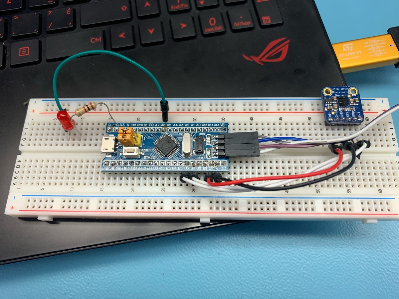
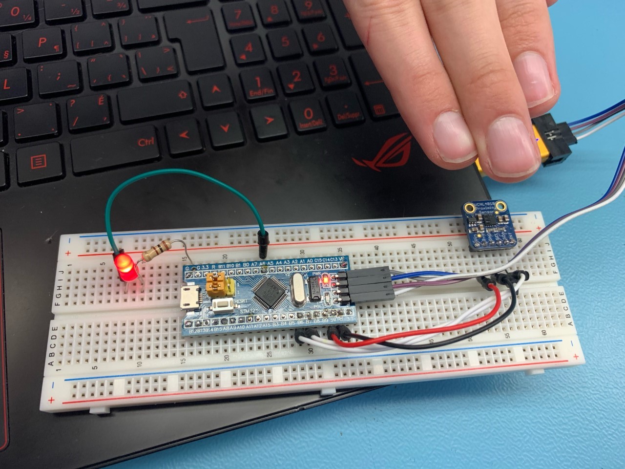
Progress Report: Everything is going on track and I have gotten the STM32 bluepill and used it to complete my breadboard. I had some issues while getting my breadboard to work since the STM32 was not able to find the sensor. This was fixed by setting up the I2C pins on the STM32 and I had to fix some of my soldering. I had some help from my partner Rob in order to do this. The only notable change I made to the project is that I changed the PCB design. I realized that my older design would not have functioned as intended and now, after fixing it, the board should run as intended. Link to the updated PCB designs can be found here: Link
(Week7) Oct/17/19
Breadboard, PCB, and Schematics all have been made. Link
Progress Report: Everything is going on track, however I am still wating for my STM32 bluepill to come in the mail. It should arrive by Monday October the 21st. Once I get my bluepill, I will be able to test my connections to ensure my board will work properly. The only problem I currently face is that i’m not sure what the output pins are on the bluepill, but this should not be a problem once I can sit down and experiment to see what works. No changes have currently been made to the budget and everything is on schedule. I will work over the reading week to ensure I can meet the deadlines.
(Week5) Oct/3/19
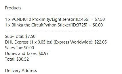
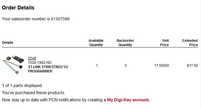
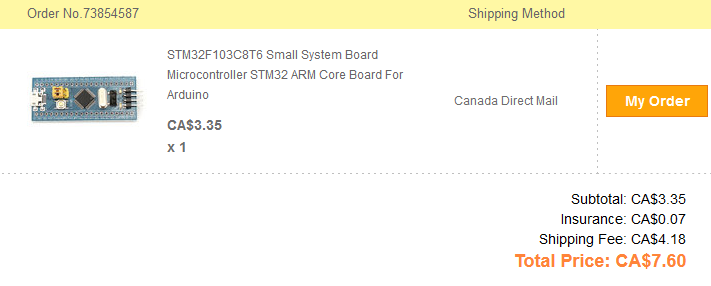
Parts have been ordered and the proof of purchase is as follows:
Sensor:
V2 Link:
BluePill:
(Week4) Sept/26/19
Budget Compleated Link
(Week3) Sept/19/19
Schedule Compleated Link
(Week 2) Sept/12/19:
Proposal Compleated. Link
(Week 1) Sept/05/19:
Repository Created!